Changing the harddisk in JVC MP-XP741
(This page last updated: 19 May 2007)Changing the hard disk in the JVC MP-XP741 isn't quite as easy as it is in e.g., the Toshiba Libretto 110CT.
In case of the JVC, almost the entire PC has to be taken apart.
Ah yes and you'll loose your warranty. Well, I couldn't care anyway since I got mine from a German store (who didn't want to deliver to the Netherlands) through a friend whose spouse works in Hamburg; somewhere in between those steps my warranty has vanished.
But perhaps you do care......
I found a hint referring to the previous model 731 here (in Japanese; use Altavista Translate to make it reasonably legible English, or enter click here to obtain English directly). I've shamelessly copied some pictures of that web page here.
However, for the JVC741 it wasn't as easy as outlined on that web page.
Below, the procedure is outlined I've followed some twenty times now.....
Safety torx size 6 problem
First of all, my 741 did not have plain Philips screws but so-called safety-torx screws, presumably size 6. You can forget to be able to open the case if you have no fitting screw driver for this. After having waited several months for the local hardware store nearby to supply me with a fitting screw driver (to be found nowhere in Amsterdam or even on Internet), I decided to taka a chance and applied a small file to a spare "plain vanilla" mini-screwdriver I had lying around. The result is shown here:
Using this tool, I could finally unscrew the 4 safety torx screws in the bottom of the JVC.
Getting to the hard disk
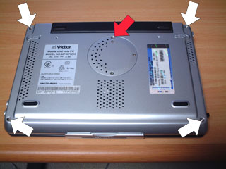
Now the procedure to change the hard disk turned out to be roughly as follows:1. Remove ALL peripherals and batteries, including the standard battery which is attached with one plain screw (red in picture below). The white arrows point to the 4 safety torx screws
2. Remove the round memory cover too (3 small screws), and remove two wires (black & gray) from under the yellow (?) scotch tape on the PC-card unit. These wires are probably power leads to the display and need to be loosened to provide space to move the display set out of the way
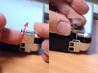
3. Remove the hinge clip-ons
4. Loosen the 3 keyboard clips, above/between o ^ / F1, F6 / F7 and F12 / Pause, and lift the keyboard. Then loosen the two flat cable connectors (the small one from the track point first) by very very gently moving the fill plug down and pulling the cable out.
5. Now remove the video connector (upper left), and three other connectors upper right, lower left & right (blue arrows in picture below).
As far as the video connector is concerned, you can also wait a little until the heatsink is gone. Be very careful with this connector
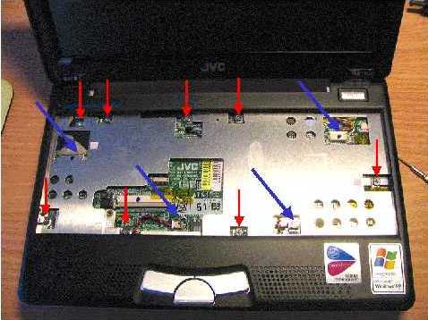
6. Remove 8 screws (red in picture above) from the heat sink
7. In the back to the right, in the hold of battery #1, there's a small latch. Push that in with a small screwdriver and then wriggle the upper case a little until the back gets loose. Now you can gently push the upper (black) part of the case, besides the mouse buttons, to the back while simultaneously lifting the case here, so that the two clips at both sides of the mouse buttons get loose. The left one is last
8. Now loosen two screws (red arrows) on the right half of the mobo. The black screw (blue arrow) holds the hard disk and can be unscrewed too
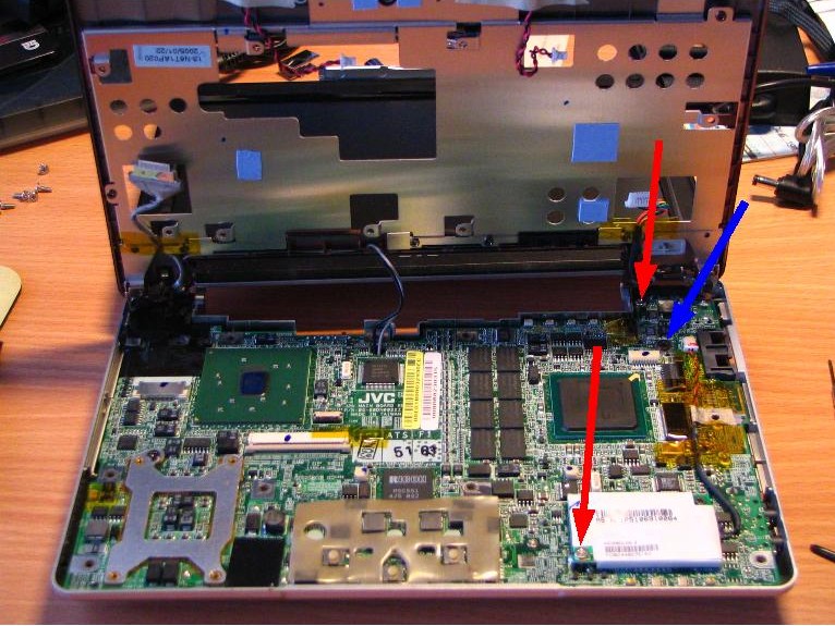
In the picture you can see a few specks of blue heat conducting "tape" that connect to the CPU & some other chips
9. Bend the right side of the case a little to make space for the audio plugs to come out and pull the mobo upward at that side. Push the PC-card button in, move the mobo a bit and it can be completely lifted out of the lower part of the case
Now, take good notice of the small diagonally placed microswitch under the mobo indicated with a green arrow; it serves for signalling presence/absence of battery #2. It is very fragile!
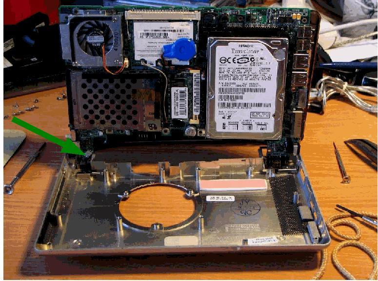
10. The hard disk can now be pulled out of the IDE connector. Under the mobo, lower left in picture above, you can see the yellow tape which holds the display lead wires (the grey one is clearly visible)
11. Insert your own hard disk (use only 9.5 mm thickness HD) and reassemble the JVC in reverse order. Be sure that the microswitch (green arrow) is not forced out of position!
Obviously your warranty is gone now :-)