I think wiring is one of the most difficult ietems in creating a model realroad layout. When I started building my first layout, I gradually bought tracks, switches, houses and signals. Each time I bought something I connected it. The result: spaghetti. Worse, when something was wrong, it took great pains to find out where it went wrong and to find back the wires.
I discoverd that very careful planning is required for wiring. This page halps a little bit in this planning process. After three years I move to another house and I will have to rebuild my layout. I will use digital wiring and will share my experiience in future.
Normally under you layout it is dark. After using pocket lamps to create a little bit light, I mounted two TL lamps under the layout. This really works excellent.
Designing wiring starts with designing the layout. It is not necessary to know the exact dimensions, but you must know:
The most important part: plan for the future! If you use one power supply now, but will use two or three in future, plan now for three and make well designed connections. Later you can split the whole stuff in two or three separated circuits with their own power supply, wihout completely rebuilding all stuff.
In the picture you see a schematic layout design. In it two power circuits are drawn in the colors red and blue. The green vertical lines represent power interrruptions. They are used to separate the power circuits and to create stop sections. A stop section is 36 cm on my hO layout. For Marklin engines, you must take into account that in some steam engines the power contact is under the tender.
You also can see that each track is numbered. (S1, ...)
Some special constructs: Track S1 has an isolated part. This allows me to use this for pendel trains. The train arrives at track S1. The engine is decoupled and stops at the end of the track. Fron S18 a parked engine comes to pick up the train.
Here you see a partial switchboard. It is reduced to approximately 40% of its original scale. The colored circles are push buttons. Note you see a lot of them and in fact this determines the size of the switchboard.For the switches the layout does not provide enough space. The blue rectangles are used for tracks that can be used in two directions. For instance track S4 can be used in east-west and west-east direction. If you go from east to west, of course you should ignore the stop section for signal Si4. For that reason I included switch RS4.
Note that all switches and signals have a unique number.
A practical tip: If you ride in dark you won't see anything on your switchboard. Therefore I included two 16V lamps in the switch board. There is a small screen between the layout and the switchboard to prevent these lamps to illuminatie the whole layout excessevily.
 |
On the left you see the wiring scheme for a
principal signal. Here you also can see my preference for epoche II. Because the scheme is
in Dutch, a simple glossary:
The red button is connected to the brown common lead (O in Marklin terminology) on one side. On the other side it is connected tot the coil that sets the signal red (10). It is also connected to the feedback (1). If the engine passes the signal, it will set the signal to red automatically. The green button is also connected to the common lead and to 11, that sets the signal green. Points 6 and 7 on the signal control the stop section. Optionally I use a yeoow button to allow the engine to pass the red signal, or to move the engine a little bit. Between 4 and 5, you see a resistor 1,5kOhm, 1/4W. For elder digital engines this is required to prevent the engine from loosing direction and speed information. For new engines this allows to change the decoder settings (speed, direction, light) while the engine is actually stopped. So here you see I prepaerd for riding digital. 14 is the power supply for the signal. In the lower picture you see some implementation details. I use a connection strip that is normally used for 230V power systems. In Dutch it is called kroonsteentje. I do not know the English word for it. As you can see I carefully defined each position. On the top side you see the layout side, on the bottom you see the connections to the switchboard. |
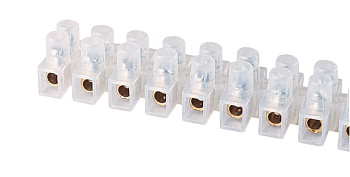 |
Here you see what I mean by kroonsteentje. It provides screw connections, which is earsier to use than soldering. I use blank wires to connect adjacent strips if necessary. You buy them at any shop where they sell do-it-yourself stuff for electrical wiring in strips with twelve positions. They can be cut and mounted very easlily. |
 |
In this situation a switching signal (rangeersein) is added.
The basic rule is that you may proceed only if both the main signal and the switching
signal show green. For switching actions you may proceed if only the switching signal
shows green. To accomplish this, the stopsection is connected in serial to the main signal and to the switching signal. If the switching signal shows green, you may start a switching action by pushing the yellow button. Lets follow the wires. At point 9 the power is available. It goes through the switching signal, which behaves like a switch end exits at point 8. So, no green switching signal, no power. Then it enters the main signal at 7. At 6 it is connected with the stop section. Between 6 and 7 the yellow button forms a bridge that may short circuit the main signal. The rest of the circuit matches a simple main signal as explained before, In the bottmim figure you see again the details with the kroonsteentjes. |
 |
Here is a sample with a direction switch. The direction
switch is a bistable switch, with a left and right position. It forms a aprallel circuit
with the power circuit of the signal. If you are rich, you also can use relais instead of the direction switch. The relais can be acitvated by the engine entering the block.In this case if the engine passes the feedback from east to west it switchs the direction switch. If it passes from west to east it sets the signal red. |
Several methods exist to keep wiring decent. I have not yet been succesful enough to advise you. Several concepts are mentioned in literature: Use a ring for the common power supply for each power circuit. Use kroonsteentjes to connect to the ring. You can use several means to tie wires together: Plastic electricity tube Professional power guidance materials Tie ropes Tie ropes have the disadvantage that it is not always easy to add additional wires. I will trie next time screws with a ring on top. I think that using intermediate distances of 20-30cm should work. Keeping the wires no longer than necessary should help a lot as well.
Page updated on 24/02/2002
Copyright © 2002 Rudolf Jan Heijink
