 ..............
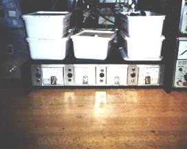
MICROWAVE CONTROL BOX
..............
Actually the name microwave control box is a little misleading as the highest frequency to be found inside this device is 50Hz. However the box serves the following purposes:
1. Power supply of mast-mounted microwave transverters (2,3 GHz - 10GHz)
2. Indication of transverter output power
3. Control of multi pole coaxial relay for multi band feed
4. Interface between transverters and transceivers
Power supply of mast-mounted microwave transverters (2,3 GHz - 10GHz)
With the introduction of solid state amplifiers in my microwave transverters the need to provide a separate power supply of the transverters arose.
The GaAs-FETs in the PAs normally requires 10-11V, but if this voltage has to allow for regulation and protection circuits, then the supply voltage can not be allowed to drop under approx. 13V.
This becomes a problem if the supply has to be transported to a mast mounted transverter. Because of the voltage drop on the supply cable a normal 13.8 V supply is no longer sufficient. Furthermore I wanted to construct a power supply with sufficient regulation capabilities to be able to run under adverse conditions (i.e. running off a badly stabilized generator).
I therefore built a 15V supply, The stabilized voltage is derived from a separate supply, so that the un-stabilized voltage can be allowed to be loaded down to approx. 16V if needed. Unloaded and with stable mains supply, the un-stabilized voltage is 22-24V.
Indication of transverter output power
In order to have a central control of the transverters, the box is equipped with metres that indicates the feed back provided by the output directional couplers in the transverters. Furthermore LEDs show wether the transverters have been switched to TX.
Control of multi pole coaxial relay for multi band feed
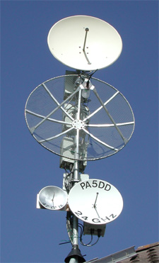
In order to make an efficient use of antenna mast space, it becomes desirable to make use of a parabolic dish with a multi band feed for the microwave bands. If at the same time the transverters are placed in the mast to minimize cable losses a need for switching occurs.
Fortunately multi pole microwave relays are available e.g. TRANSCO 14300, which is a SP4T relay. In order to make the switching as seamless to the operator as possible, I decided to make some control logic, that switches the relay to a given band when the transverter of that band is switched to TX. Afterwards the relay stays in that position until another transverter is switched to TX.
With this system the operator simply has to flick the PTT on a given band to acquire a connection to the multi band antenna.
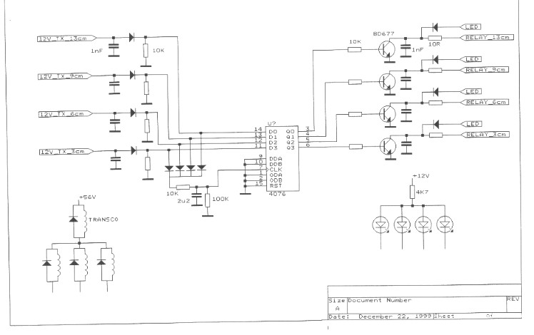
The control logic was realized with D-flip/flops, connecting the TX/RX switching signals (e.g. 12V_TX) output signals of the transceivers to the inputs, and using the RX-to-TX transition of any of the signals to clock the flip/flops. Check out the schematic.
Interface between transverters and transceivers
The box acts as interface between the transceivers and the transverters:
The transceivers are delivering the TX/RX switching signals (e.g. 12V_TX) signals into the box using phono plugs.
Every transverter is connected to the box using a 4-wire cable fitted with standard connectors carrying:
- Power supply
- RF output feedback
- TX/RX switching signal (12V_TX)