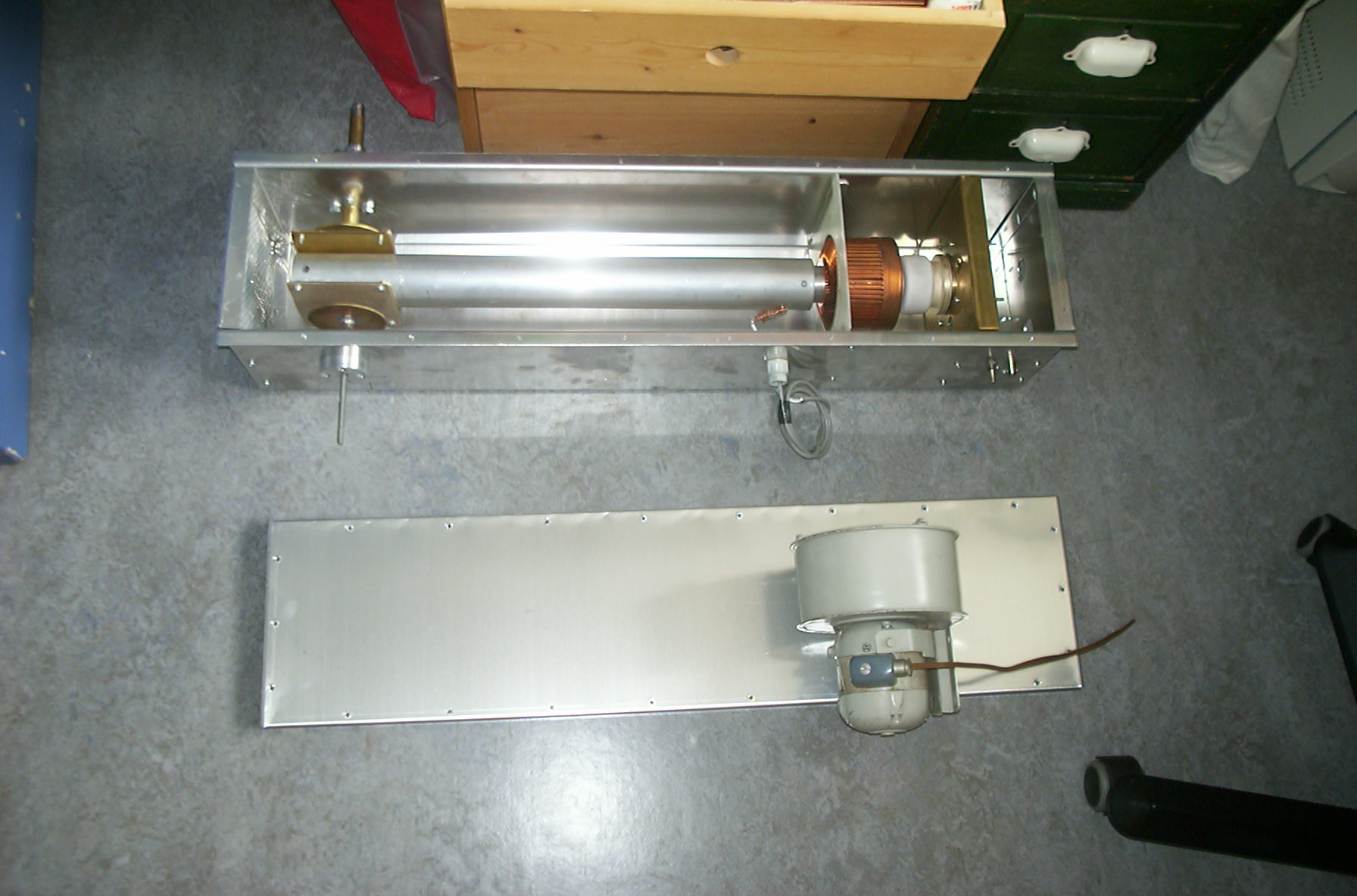
The original RX1AS PA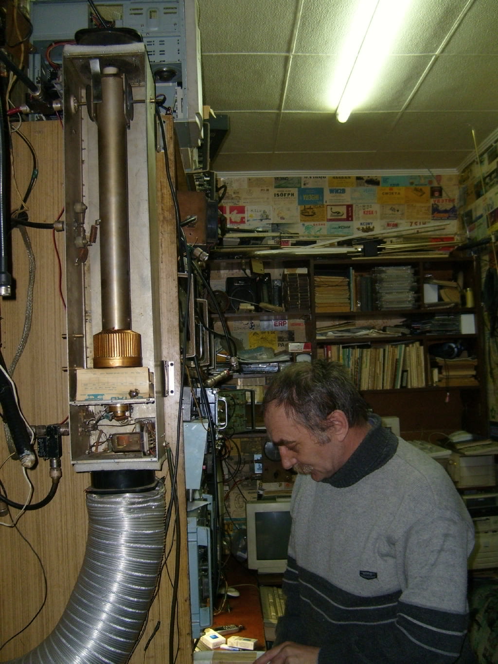
Picture by OH5LID
RX1AS style 144 MHz PA with GS35b
Project started: 20031110
Project finalized: 20040820
Project status:
Box finished 200312
Mechanical parts finished 200403
Bias/Heater circuits fitted 20040814
Power supply modified for grounded-grid 20040815
PA tested with HV & bias 20040815
Input RF circuit 20040819
Final RF test 20040820
Thanks for help and advice to: PA7JB PE1PFW PA2DW
Do not use this amplifier without a proper lowpass filter ! (eg. a coaxial stepped impedance filter available from Arie PC7M ). The combination of the halfwave resonator, and the capacitive loading does not offer much harmonic supression.
Construction links
|
The original RX1AS PA |
|
PA4FP - sells parts
OK1BAF - a similar construction with a bigger tube
DL4MEA - not a RX1AS construction, but the manual has many good tips
EA3AXV - not a RX1AS construction, but has a good input circuit (L2 was reduced to 3 windings in my PA)
F1CXX - not a RX1AS construction
G3SEK - bias circuit and how to arrange metering for grounded-grid (page 6)
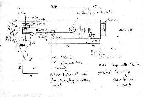
This amplifier can be made on the "kitchen table" with simple tools. There are only two machined parts: The tube/stripline adapter and a teflon termination in the output coupler. The teflon termination can be made with a power drill and a strong knife. The stripline adapter is available from PA4FP.
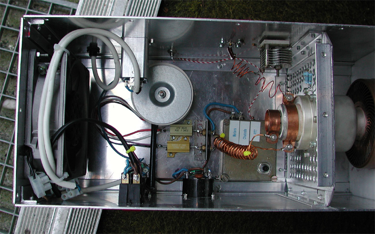
Output coupler
The output coupler is made with parts from the local hardware store (idea by
PE1PFW):
Outer tube is 1/2" copper water pipe, internal diameter 12.7mm. Inner tube
is a solid brass rod, diameter 6mm. The female N-pin is removed from the plug
and soldered to a hole drilled at one end of the rod.
The wall feedtrough is a standard brass 1/2" water pipe fitting, which is
drilled trough to allow the pipe to pass. A slot is cut
in the external tread to make it press against the tube when tightened.
The loading disc is made with a 83mm (3 1/4") hole cutter in a brass plate.
Input circuit
When I got around to making the input matching circuit, I stumbled over a
posting on the AMPS
reflector by OZ5TG recommending using a 150 Ω resistor (from cathode to GND) to simulate the dynamic
resistance of the "live" tube.
This value worked fine for me. I was able to tweak the input circuit
(L-C-L T-network) copied from EA3AXV
using an MFJ SWR analyzer. The finished PA tunes
nicely to a perfect match on the input.
By tweaking the coils in the "cold" circuit I avoided using a
variable "floating" capacitor in series with the first coil. I think
this has saved me some losses in the input circuit. By the way - I never decoupled the heater towards the cathode. It
seems to work fine without it.
Heater
If you apply the nominal heater voltage to a cold tube of the Russian
types (true at least for GS35b) you will far exceed the allowed
heater loss, because the cold heater will have less resistance, and
you will eventually blow the tube.
There are several ways of dealing with this:
1. Apply the nominal heater voltage trough a resistor, which is
bypassed after a delay (used by PA2DW)
2. Apply a higher heater voltage trough a permanent resistor. Choose
the resistor value such that the rated heater loss can never be
exceeded (about 18V / 1.8 Ω for GS35b). You will suffer some power loss
in the resistor(s), but they will keep you warm on a cold day (used
by PA5DD).
3. Choose a too small heater transformer, that will saturate the core
when connected to the cold heater. Could be combined with a small
resistor (proposed by PE1PFW).
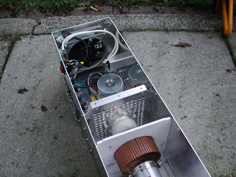
Cooling
A typical axial ventilator (e.g. PAPST 4650N) delivers 160 m³/hr (94 CFM) which is enough for colling the GS35b. Of course the ventilator only delivers this volume at low back pressure, which is why I decided to mount two blowers. Depending on which anode loss, duty cycle and enviromental temperature you intend to operate with, the second blower can be left out. A real killer is dry air, be careful when operating in places where the humidity is low.
The air flow should be from the cathode
compartment to the anode compartment, which is the standard direction (air
intake over struts) of 119x119mm axial blowers in the configuration, that I have
choosen. Note that axial blowers cannot be turned around, without generating a
lot more noise, as the fan gets too close to the mounting wall. I learnt this the
hard way, as I had two strong odd-size 127x127mm blowers, which have reverse
airflow (air exhaust over struts). Not being able to turn them, I had to
blow hot air into the cathode compartment. This cost me 3 blown bias circuits
over 2 years of use. It is worth noting, that quite some power is dissipated
in the bias circuit. Although not shown in the photos, I have also mounted a
heat sink on the top of the bias metal case. Cooling air circulation around the
bias circuit
is vital.
As you can see from some of the constructions links, others prefer to use a
tangential ventilator blowing into the cathode comnpartment, or the separation
space between the grid and the anode.This will work fine aswell.


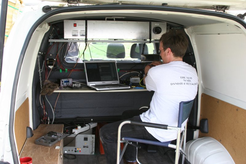
Portable use
BACK TO TECHNICAL