|
|
|
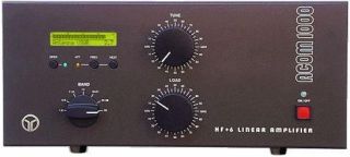
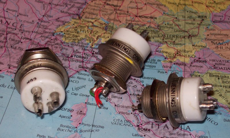
I modified my ACOM 1000 to work on 70 MHz. The solution uses electric band switching, such that both 6m and 4m operation can be maintained. The modification uses two Jennings RJ1A vacuum switches, available surplus for around 20 a piece. This modification is not straight-forward and requires a fair amount of skill and proper tools.
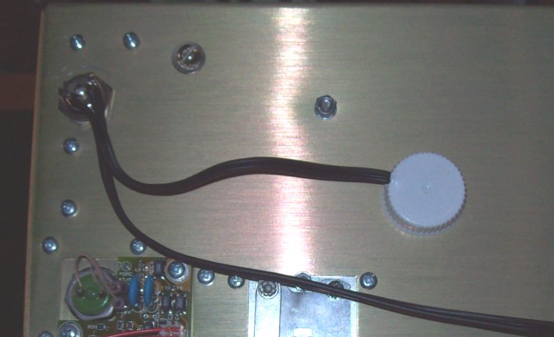
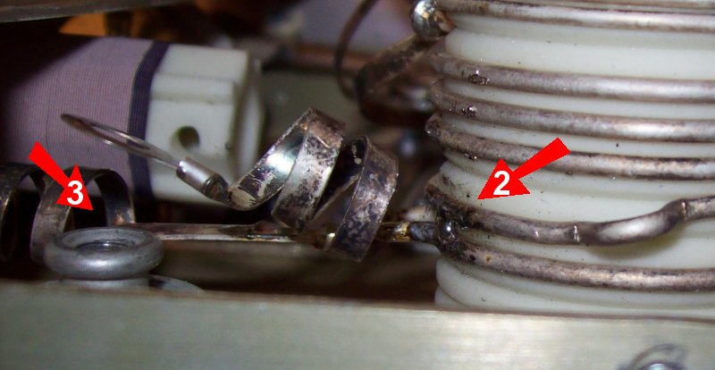
You can also perform a simple modification without the band swithcing. This
will not allow you to use the amplifier on 6m. This modification should be
obvious from these two photos:
TUNE
LOAD
The modified amplifier will deliver in excess of 800 W on 4m with an input of 30 W. The tuning is a bit critical as it is on 6m. The tuning aid appears to work on 70 MHz, but read the section at the end of this page for more on this subject. My settings when tuned on 4m are TUNE 25 LOAD 15. I did not measure harmonic suppression, but I'm pretty sure you will need to make a low pass filter for the amplifier, when using it on 70 MHz.
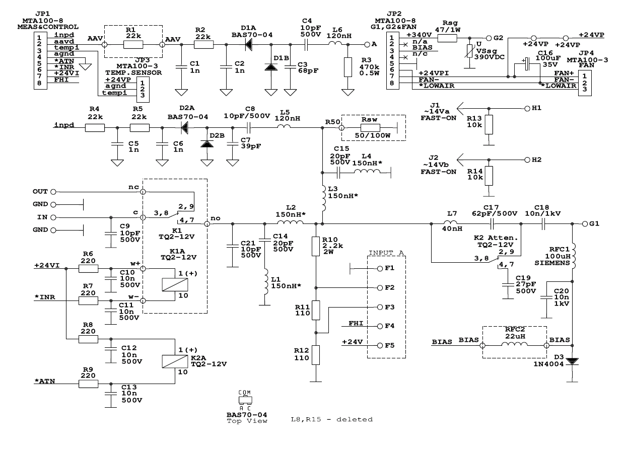
The principle of modification is to reduce the two coils in the Pi-L output matching network enough for the capacitors to make reasonance on 70 MHz. The input circuit is broadband resistive, so it does not have to be modified (but read the section at the bottom).
The modification step-by-step:
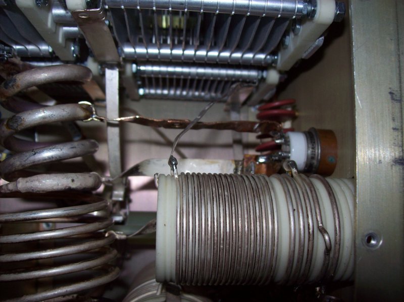
On the output side (load coil) mount the switch to break the connection between Lf2 and RFC3. Connect the "COM" port of the switch to RFC3, and the Lf2 to the "NC" port. Mount a lead to the "NO" port of the switch and solder it two windings up the loading coil LL. When the switch is activated you will in effect bypass these two last windings.
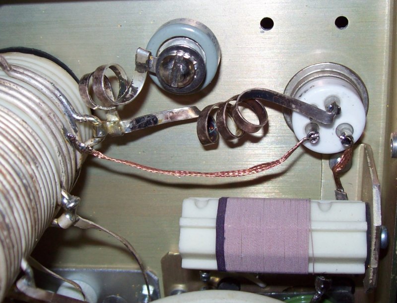
Now mount the second switch to short circuit two windings on the tune coil LP2. Use the "COM" and "NO" ports. Use some heavy copper strips to maintain the Q in the tank circuit. You will need a butane tourch to do the solderings.
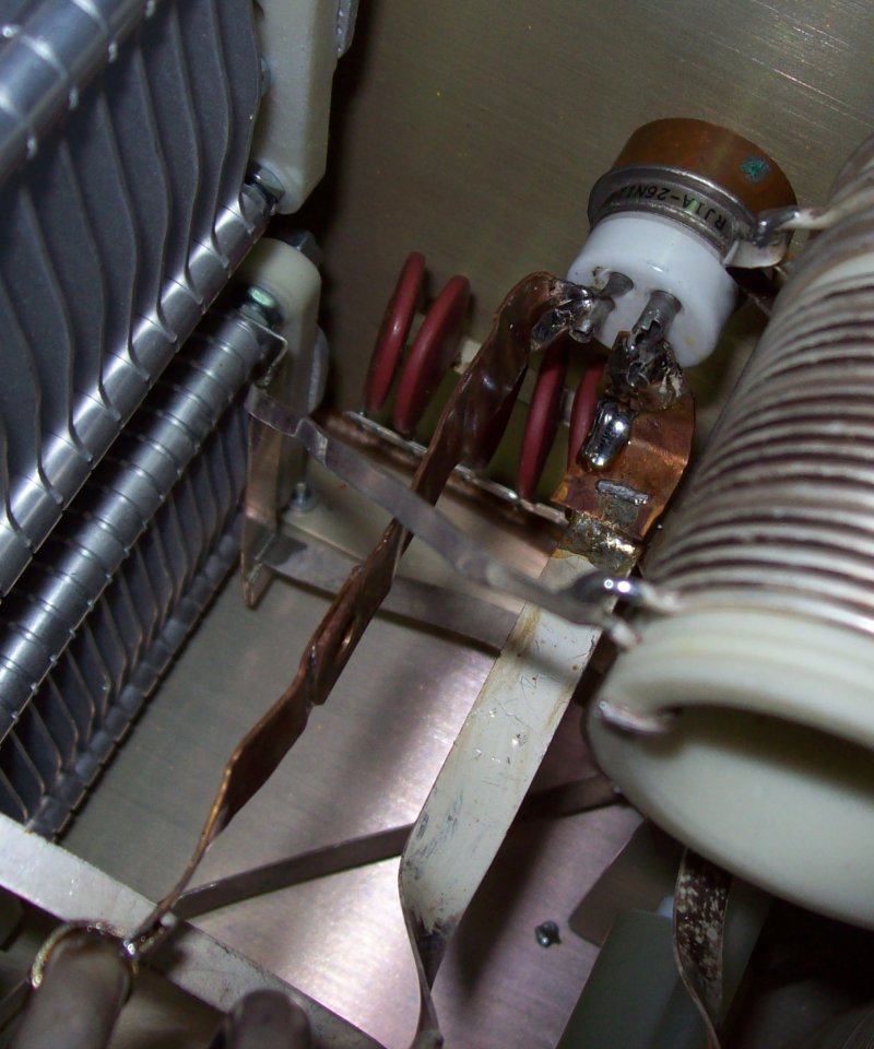
There is not much room for the outside part of the second switch. Therefore note the inserted copper spacer (9.5mm), and the isolation cap on the outside.
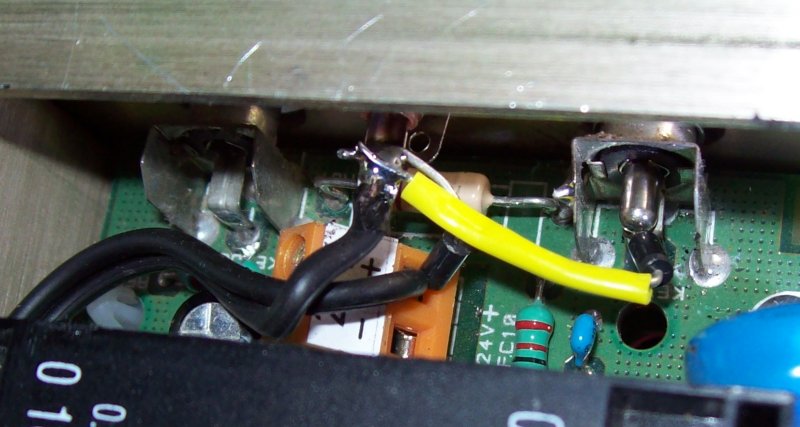
+24V for switching the relays is available just next to the PTT phono plugs at the back of the amplifier (Do not use the -24V connection - it is keyed for use with an external blower). Connect the -24V connection of the relay coils to an extra phono plug on the back. The band switching relays can now be keyed by connecting the phono plug to ground. Add a diode to connect the new phono plug to the PTT IN plug, then you can key both the amplifier and the band switching relays using the new phono plug - ie. a seperate 4m PTT input.
Note that keying the relays directly is a bit crude, and the PTT circuit in your transceiver / transverter should be able to carry the current (approx 150mA). Remember to mount diodes over the relay coils to kill the induction switching pulse.
Finish off by the disabling the electronic bias switching (EBS) as described in the section below.
The tuning aid and the input circuit
Whether the tuning aid can be trusted on 70 MHz is a bit of a complex matter, but wtih me it seems to provide a suitable loading factor, when used for tuning when the attenuator is activated. This attenuator is actually a frequency dependent network of a coil and two capacitors (L7, C17, C19), and not a resistive attenuator. No doubt this has been done to balance the attenuation against the frequency dependent impedance of the grid.
The input SWR is fine during operation on 70 MHz, but around 1:3 when the "attenuator" is inserted. If this SWR value causes your transceiver to decrease the output, tuning with the attenuator might prove difficult.
The tuning aid works by measuring (D1A, D1B) the peak RF voltage on the plate, There is no reason to assume, that this measurement should not be valid on 70 MHz. The readout of the tuning aid is triggered by the detection of input power (>5 W), and this is where the problems start because the frequency dependent compensations built into the input circuit attenuates the amount of 70 MHz signal reaching the input detector (D2A, D2B). Actually the bad SWR introduced by the attenuator aids the input detector.
The lack of input power detection could also affect the electronic bias switching (EBS) of the amplifier, as a 4m drive signal is more likely to be within the EBS transition zone. You are therefore encouraged to disable EBS by short-circuiting R11 on the MAINS PCB, and to re-adjust the bias setting (RP2) to around 120 - 150 mA. This modification will decrease the amplifier gain a bit,. and increase the required drive power.
I assume that the computational link between the plate RF peak voltage and the tuning aid readout is dependent on whether the attenuator has been switched in or not. The resulting loading value might therefore not be good if the attenuation level is different from that of the other bands.
The link might further be dependent on the outputs from the input signal detector and the frequency detection circuit (INPUT-A) making the whole thing a bit speculative and complex.
I guess the thing to do is to tune and readout the plate peak RF voltage from the display at full carrier output. This value should be about 10%, but not much more below the loaded DC plate voltage, which can also be read from the display. Load looser (turn right) to increase the plate peak RF voltage, or tighter (turn left) to decrease it (always re-peak the tune knob for max. power.after each change of the load setting).
Amplifier trips
The ACOM 1000 has extensive protection circuits that will interrupt the amplifier operation, if a fault is detected. Should you experience this, here is some advice to find the cause:
1. The ACOM protection circuits are faster than protection circuits in other amplifiers. If there is a bad (=intermittant) connection somewhere in your RF feeder line or the antenna it will continously trip (usually ARC FAULT), although it might not be possible to measure the error. These kinds of trips have often been reported on the YAHOO reflector, and always resulted from a fault in the feed line. http://groups.yahoo.com/group/acom-list/message/28882. ALC power spikes. Many modern transceivers have ALC with a considerable attack time. If the power is regulated this could result in a leading edge power spike enough to trigger the normal protection circuits in the ACOM. You will have to either disable or modify the ALC circuit to counter this. One way of disabling the ALC is to provide a constant negative DC voltage to the external ALC input of your transceiver. Another way is to run the set at full O/P trough an attenuator. http://groups.yahoo.com/group/acom-list/message/2885
3. If the tripping is due to flash-overs in the tank circuit (ARC FAULT), then a trick is to load a little bit harder (turn left on LOAD knob). The tuning is quite critical. It only takes a few mms of movement for the loading to change significantly (always re-peak the tune knob for max. power.after each change of the load setting).
4. The ACOM is prone to RFI via the supply line, that could result in trips. A snap-on ferrite is highly recommended. http://groups.yahoo.com/group/acom-list/message/2657