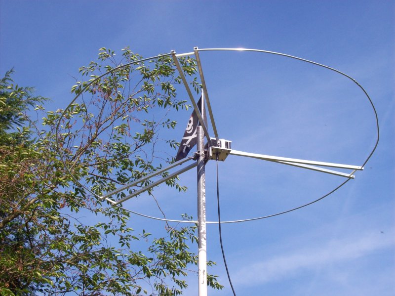
Big Wheel for 70 MHz
The Big Wheel antenna is a good choice as a beacon antenna, as it has by far the most omni-directional patten for any horizontally polarized antenna. It is not a straight-forward antenna to construct, and it is not being offered commerically for 70 MHz. I therefore decided to buy a Big Wheel for 50 MHz manufactured by WIMO and cut it down for 70 MHz. The Big Wheel is intended for the future use with the beacon PI7EPO.
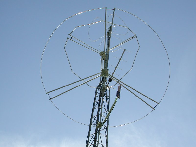
Here's a selection of Big Wheel antennas used at the
OZ7IGY beacon. The largest wheel is the WIMO 6m version.

In order to familiarize myself with the antenna I first created a
NEC2 model
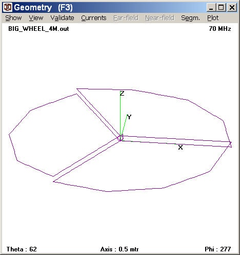
Despite many myths the gain of a Big Wheel is in the order of 1.5 dBi (-0.65 dBd).
|
|
|
These are the dimensions (length of materials before assembly) that I found after an iterative cut-down
of the antenna .
These measurements only apply to the WIMO 6m
antenna.
| Length (mm) for 70 MHz |
Length (mm) for 50 MHz (original WIMO) |
|
| Feeders | 1078 | 1493 |
| White spacers | 140 | 192 |
| Arches | 2117 | 2900 |
These dimensions were held conservatively, such that you will not cut the antenna too short. If you need the antenna further upband from 70.000 MHz you should shorten them proportionally. In any case the Big Wheel shows a large SWR bandwidth, and the reasonance can be shifted quite far by moving the shunt. As you move the reasonance away from the ideal frequency you will see that the dip becomes less deep.
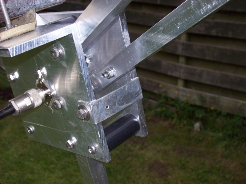
The shunt needs to be fitted flush with the hub side, and closer to one of the feeders. A wider shunt is probably also a good idea. Moving the shunt back and forth along one of the hub sides is a good way to tune the antenna. Tune the antenna with the mast passing trough the wheel. Most likely you will not be mounting the antenna on the top of the mast tube, so you need to take account of the capacitive load of the mast when tuning the antenna.
Here's a photo of the hub with my shunt mounted
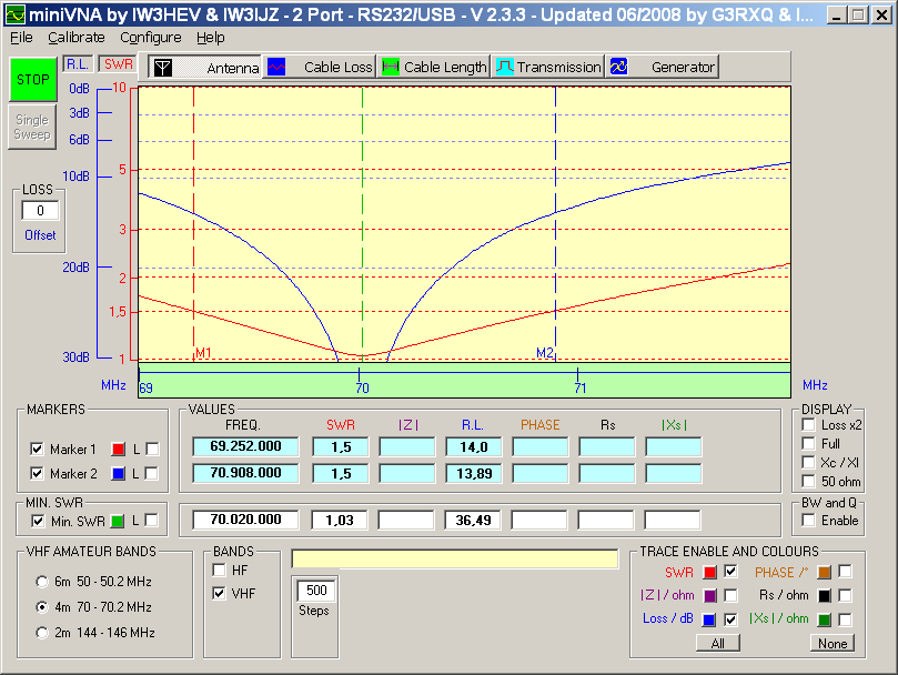
Resulting in these SWR plots
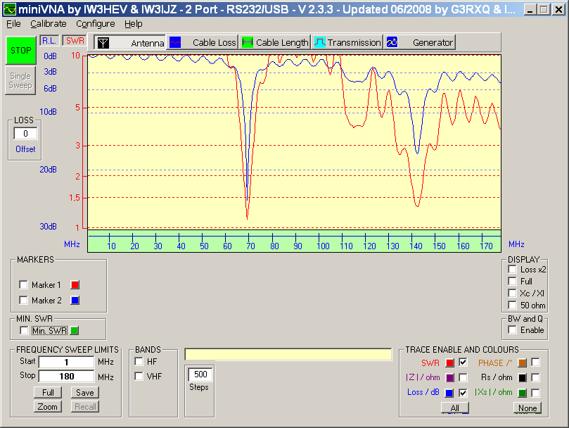
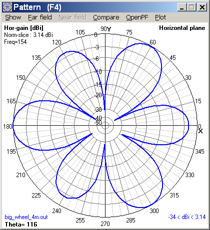
As you can see this 70 MHz Big Wheel can also be used for 144 MHz, but the radiation pattern will look something like this:
Here's the antenna in the test position
