I need to replace my 6m antenna because of tear and wear. At the same time it
would be nice to get a 4m antenna up the big mast. A dual band yagi is an
obvious solution.
The first design to examine was the
IW0FFK design. It did
not exactly fit the bill because it is a bit too long for me, and the dual feed
points are unpractical.
Next option were the YU7EF
designs. They suffer from the fact, that priority was given to 6m
performance. Ideally I would prefer more emphasis on 4m, as this is more of a
Tropo band, whereby the gain is needed. I am also less concerned about side lobes
than Pop. On the other hand the YU7EF designs are great because they have a
common 50Ω feedpoint, something that is very convenient in a dualband
design, where a (frequency dependent) transmission line impedance match is not
an option. Instead a couple of meters of coiled 50Ω cable can serve as a balun.
So although it is new to me, I had a go of doing a design myself. I am using
MMANA-GAL
(MININEC engine) to do
the optimisation, and verifiying in
4NEC2 (NEC2 engine). I use NEC-2 for MMANA to
convert .maa files to .nec files (cut and paste from the NEC-2 input window. Delete the second line that begins with
"RP"). The MMANA-GAL optimisation is very easy to set up, and
allows for simultanous optimization at multiple frequencies.
|
Note on NEC2: Aim for a value of around 30 - 40 segments
per half wave in this frequency range. Fewer segments cost
precision, and too many invalidates the NEC-2 model, as the segments stop being
wires (length/radius ratio should be at least 8). If for some reason you need
more segments per half wave you need to invoke the EK card (Extended thin-wire
Kernel). Use the Average Gain test and the Convergence test to verify your model.
Dual band antennas will often give
segmentation check errors because two elements of different length are close to
each other. This will lead to non-aligned segments in the two elements. The trick to avoid this is to chop up the
longest element into 3 wires (GW). A central wire being the same length as the
shorter element, and two wires at each end to bring the element back to the
original length.
|
The starting point was the
GW3YDX 4/5ele yagi because it has a good balance between 6m and 4m gain. I
started by adding one extra element per band, dimensions extrapolated from the
existing directors. After optimizing on this design I transformed it to a single feedpoint (parasitic
drive element on 4m, also called
open sleeve dipole) à la
YU7EF, because I
am not too fond of the parallel
feeding solution, that
is more suited for shortwave yagis.
Used optimization parameters: Weight: Gain, SWR, F/B (bit less emphasis than
the other two). Goals: F/B = 20dB SWR = 1:1.2 Frequencies: 50.2 & 70.3 MHz
(because the frequency of lowest SWR appears to drop a bit in the NEC2
simulation)
YU7EF, Pop helped me refine the design.
I am quite happy with the simulation results of the design. Biggest concern is the
sharp resonance on 4m, and that will require attention during the construction. I'm curious how
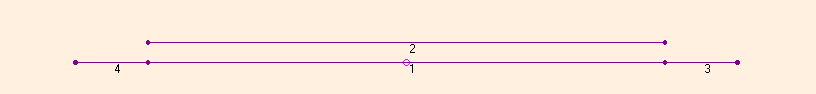
the design will reproduce in real life.The yagi is 5.4m long and uses elements
with a diameter of 12mm.

Dimensions can be seen in the simulation file
Boom (m)	Half element length (m)
0		1.4615
0.875		1.0265
1.336		1.4185	(feed)
1.376		1.011
1.749		0.990
2.311		1.294
2.758		0.970
3.505		1.338
4.425		0.9795
4.71		1.303
5.4		0.952
I will go for a light construction using
NUXCOM components and a 20x20mm boom. The distance between the two feeding elements have been fixed during the
optimization to 40mm to fit the distance between the mounting holes in the
standard electrical equipment boxes
normally used
for dipoles.
Given the fact, that the antenna is very narrowband on 70 MHz, you are
encouraged to leave the 4m dipole and the first 4m director at least 6mm longer (of the total element
length) than the values given in the simulation file. This is equivalent
to a downwards frequency shift of about 200 kHz..
Using the dimensions of the simulation and using plastic end caps the antenna
showed minimum SWR just below 70.150 when in the
test position.
How to tune the antenna
The sharp reasonance at 4m requires the antenna to be tuned in-situ, which
can be a little cumbersome, but that is the price to pay for the high gain on
both bands. You should follow these steps:
- First make sure the antenna is working as expected with an SWR dip on both
bands. The 6m dip should be better than SWR 1:1.2. The 4m dip should be 70.200
or lower.
- If needed cut the 6m dipole for best SWR at the proper frequency
(the 6m response is more or less independent of the 4m elements). Around 3
mm/100 kHz of each end of the dipole. A pipe cutter is perfect for this
job, but finish off with a file to make the cut straight.
- Now cut the 4m dipole and the first 4m director together for
reasonance at the proper frequency. Around 1.5 mm/100 kHz of of each end of the
elements.
- If needed move the boom position of the first 4m director to make the 4m
dip deeper (use two crossed tie raps to hold the element).
- Steps 3. & 4 should be done in an iterative manner.
- Be aware of things influencing the antenna. My antenna changes response as
I turn it around. If you cut the 4m SWR dip a bit too far it might be kind of
an advantage because rain will move it downwards. Remember that plastic end
caps will move the dip a bit down in frequency as well.
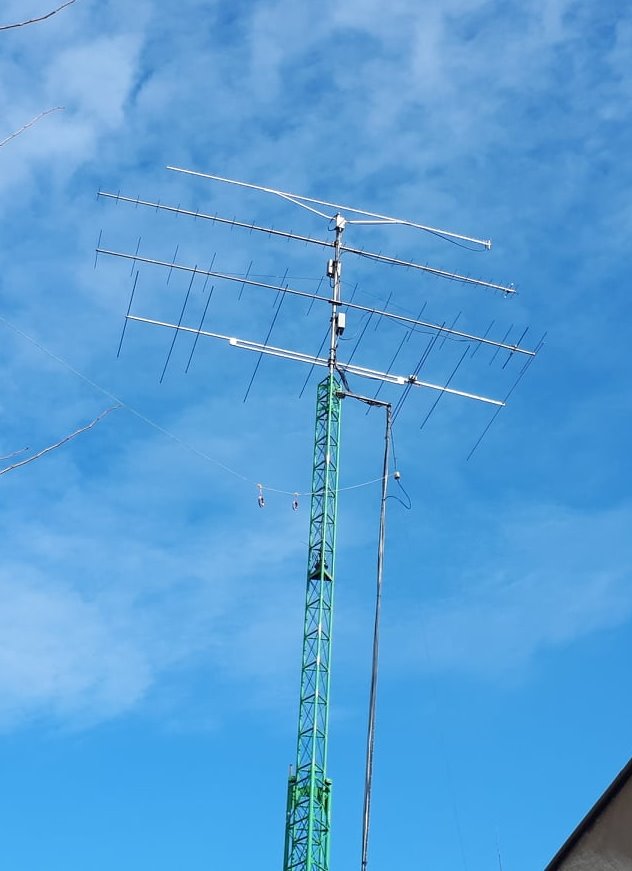
The antenna in the mast,
and the SWR curves at the antenna (compensated for 20m of RG213 = 1 dB of cable loss). The 4m response is
sensitive to objects near the antenna, rain or ice.
|
50 MHz |
70 MHz |
|
 |
 |
BACK TO ANTENNA OVERVIEW


