This project consists of two steps:
1. Upgrading my 24GHz transverter to "second
generation".
2. Combining it with a 47GHz transverter.
Upgrading my 24 GHz transverter to "second generation"
Status:
Ready 20010209
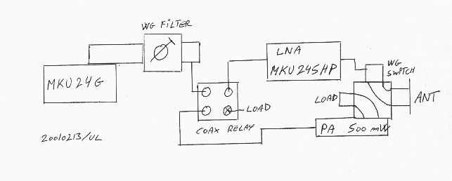
This part of the project involves the addition of a waveguide switch (courtesy of OZ7IS Ivan), and a 500mW PA (KM1H-24PA003) to my existing 24GHz transverter, which was based on a combined LNA/PA amplifier and a transfer coax relay.
The additions will give me about 9dB better TX performance, and 2dB better RX performance,
The new system looks like this:
I will re-use the transfer coax relay for switching between the amplifiers and the diode mixer (MKU24GA)
|
|
|
|
Click on the pictures for enlargement
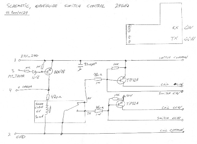
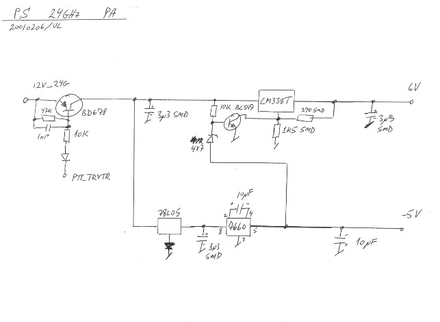
| Circuit diagram of waveguide switch control circuit.............. | ..............Circuit diagram of power supply for 500mW PA |
One problem with the KM1H PA module is that it does not include a power detector. Therefore it is not possible to generate a feedback signal to indicate the power output. As a replacement I tried to measure the current comsumption of the module during excitation, and luckily the current increases with about 10% between idle and saturation modes. Although this is not a direct indication of output power, it can be used to indicate that the module is working and has sufficient drive level. In my case I have a constant current drain on my "12V_24GHz"-line, so I can do this measurement without a seperate feedback line.
The feedback line - which is part of my standard 4-wire interface between mast & shack - is used to carry the feedback signal from the LO PA (MKU102AL) shown in the drawing below. Since this PA do have a power indicator, this signal comes for free, and is a good indication, that the LO is working.
Combining it with a 47 GHz transverter
Status:
Ready 20020610
This project idea started after I had been playing around with some numbers from my 24GHz system (DB6NT MKU12LO + MKU24GA). On 24GHz I use 432MHz as IF, because it makes it possible to filter out the undesired sideband (or image) from the mixing process. This filtering improves RX & TX performance with 3 dB.
On 47GHz image filtering is normally not attempted, and hence most receivers (and some transmitters) are double sideband. My idea was - after playing with the numbers - that it doesn't matter which of the sidebands are used on the proper frequency 47088MHz.
Magic Numbers
On 24 GHz I start with a LO signal of 11880MHz, and look what happens !
( 2 * 11880 ) + 432 = 24192MHz
( 4 * 11880 ) - 432 = 47088MHz
On 47 GHz the IF of 432MHz is inverted in the mixing process (has a negative sign in the equation), and therefore I will have to use LSB, and dial downwards on the VFO to go up in frequency. This is no big disadvantage, because most 70cm transceivers covers also 430 - 432MHz. The result is that I can use the same LO signal on 24GHz & 47GHz. This saves me the trouble of building an extra OCXO and multiplier chain.
Note by the way, that if you use 1296MHz IF, it gets even nicer:
( 2 * 11448 ) + 1296 = 24192MHz
( 4 * 11448 ) + 1296 = 47088MHz
And while we're at it:
( 2 * 24192 ) - 1296 = 47088MHz
Addendum 20030529 - QSY to 24048MHz
Witn the proposed change of frequency from 24192 to 24048MHz as of 2004 the system will change according to the following plan. The dual-system will still work together with a FT817 opened for TX below 144MHz.
( 2 * 11808 ) + 432 = 24048MHz
( 4 * 11808 ) - 144 = 47088MHz
Proposed system 24GHz / 47GHz
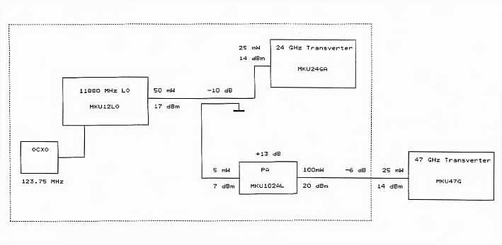
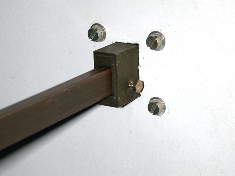
The choice exist to install a coaxial switch on the output of the LO, but I have chosen to couple out the signal for 47GHz instead. The reason for this is, that I already have the coupler and a 10GHz PA, which can be used to amplify the signal to 100mW. This also enables me to have the 47GHz transverter and antenna at some distance to the 24GHz installation, as I can now accept 6dB of cable loss in the LO signal path.
The IF line to the 432MHz rig will be shared by the two transverters. The path will be switched by a coax relay inside the 24GHz transverter box.
I encountered some problems when I tried to connect a DF9LN OCXO (Oven Controlled X-tal Oscillator) to the MKU12LO multiplier chain. The 1mW output of the OCXO proved to be far to little for connecting at the indicated place (the output of the build-in Butler oscillator). In stead I had to couple in the external oscillator signal at the emitter of T1, after removing the crystal. Probably it would be a better solution to couple T2 as a grounded-emitter amplifier, and couple in at the base of T2.
I don´t know if this problem is due to a fault in my MKU12LO, or if this is a general problem. I would appreciate any feedback on this. For example what is the output power of the build-in Butler oscillator ?
Unfortunately the above problem killed my idea of keeping the build-in X-tal oscillator as it was, and later using it to drive a doubler chain for obtaining more output on 47 GHz. My idea was to key between the OCXO (at 123.75MHz) for RX, and transmit with the build-in oscillator (at 122.625MHz). Further the 12GHz LO would be spilt for the MKU47G mixer at RX, and a doubler chain for TX.
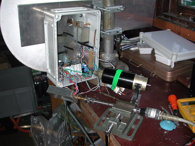
Implementation
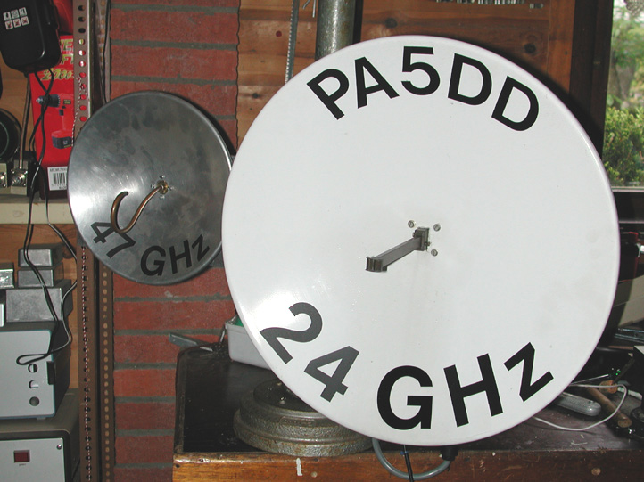
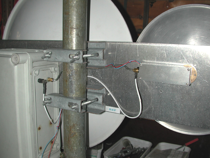
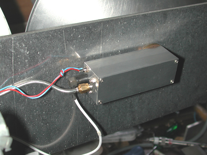
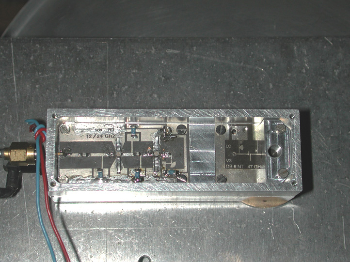
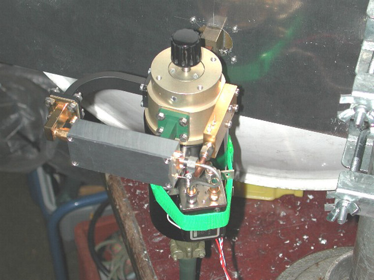
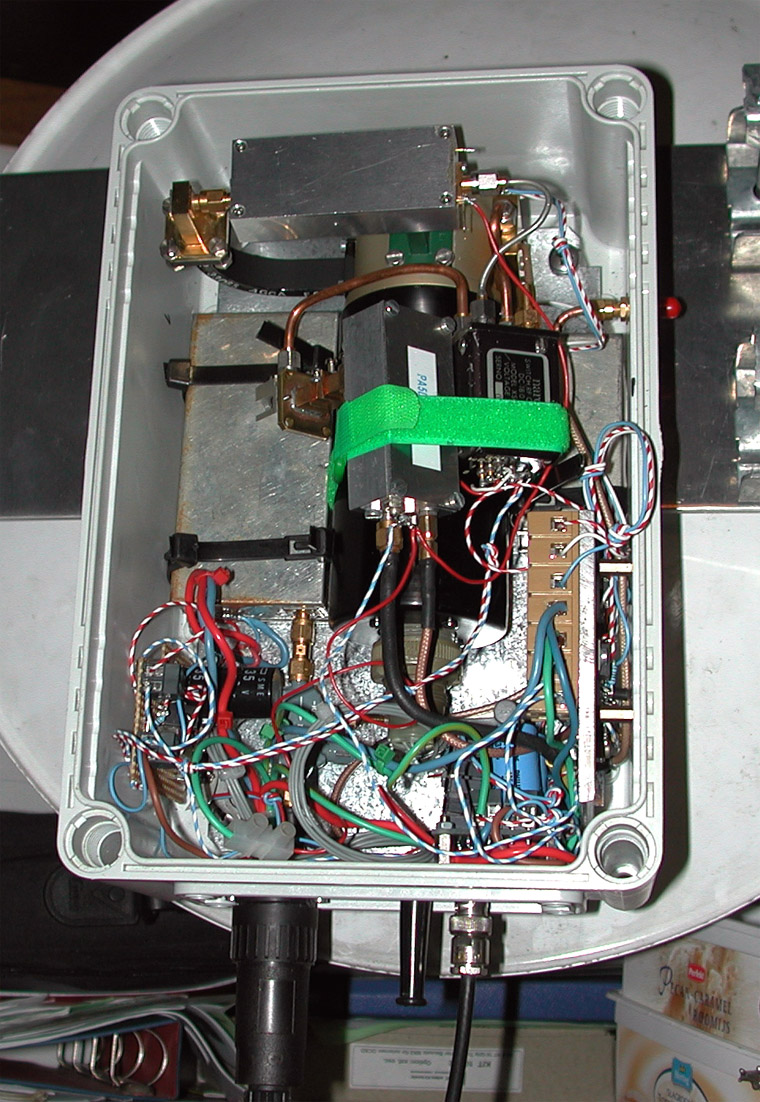
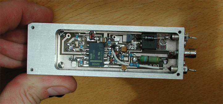
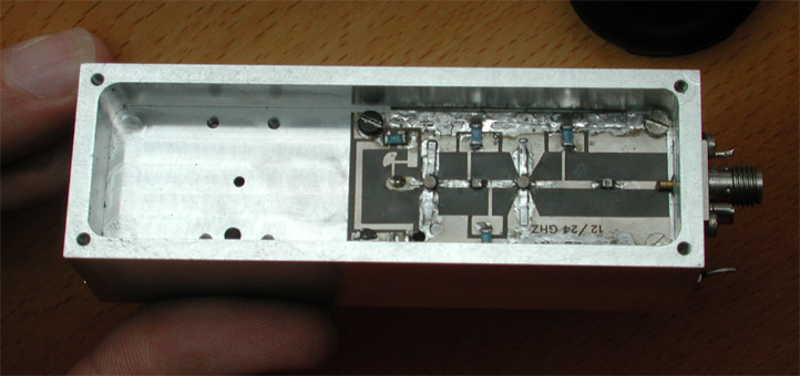
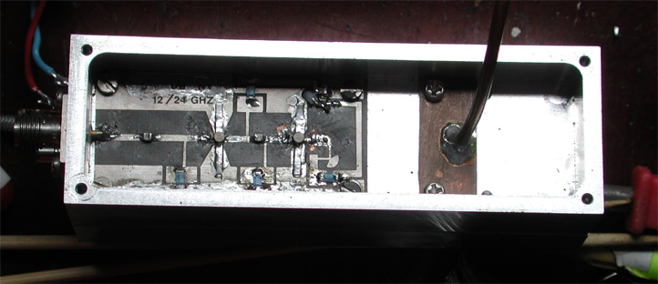
Ready (see photos):
- 24GHz transverter
- Directional coupler (10dB)
- 100mw 12GHz PA
- 47GHz antenna ( 25cm parabolic dish courtesy of OZ5DI Ejgil )
- Mast mount for the combined system
- OCXO
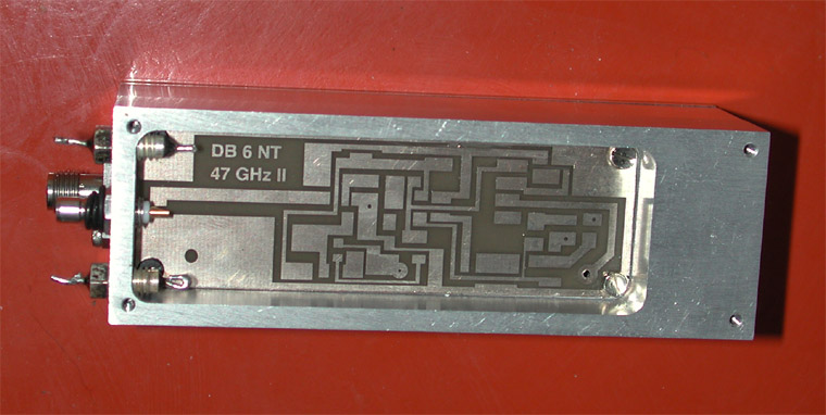
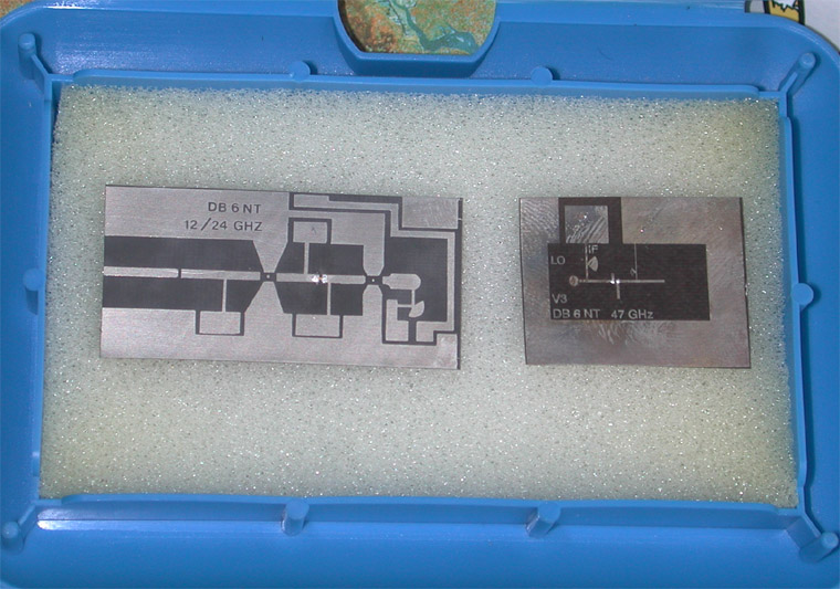
- MKU47G
(Doubler: 13mW@23GHz)
|
|
|
|
|
 |
 |
 |
 |
Contrary to earlier plans I decided to build the transverter myself. I did this with invaluable help from Bart, PE1PFW - Thanks !
Perspective
The purpose of building this 47GHz addition to my microwave station, is the possibility to make QSOs with the two home stations QRV at present in the Netherlands, namely:
PA0EHG (JO22HB) QRB 4 km
PA3AWJ (JO21GW) QRB 20 km
Futhermore Bart, PE1PFW is expected be QRV, when we finish this construction project.
PE1PFW (JO22ID) QRB 6 km
Wether it will be possible to QSO these stations with 200 µW output and 8dB noise figure remains to be seen.
The results speak for themselves:
Date     UTC  Call       Loc    QRG   2*  RSTs   RSTr  QRB(km)
20020624 1824 PA3AWJ     JO21GW 47088 CW  539    529    20
20020623 1244 PE1PFW     JO22ID 47088 SSB 57     57     6
20020612 1934 PE1PFW/P   JO22IC 47088 SSB 59     59     1