TIPS FOR OPERATING A MULTIBAND STATION
by PA5DD, Uffe Lindhardt
Being QRV on microwaves can involve being QRV at 5,6 or 7 different bands. Contests and band openings often requires fast QSY between these bands, as well as simultaneous operation on more than one band at a time (e.g. talkback). To fulfill these requirements puts high demands on the station design.
This article tries to give some hints as to how this can be done.
AUDIO & CW KEYING
In order to be simultaneously QRV on different bands, more than one transceiver is needed. As the choice of talkback varies (144 MHz, 432 MHz, 1296 MHz etc.) even more transceivers could be needed.
This naturally gives some switching problems when it comes to one headphone and one CW keyer.
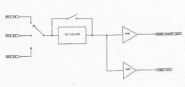
For the audio part I have made a "Headphone amplifier box" which takes the standard 200mV AF output available on most commercial transceivers as input. For the sake of standardization I have equipped all my transceivers (6 in all covering 1.8 MHz trough 24 GHz) with phono plugs for the AF output. Inside the box I have a switch to select one of the AF inputs. The input is then amplified before being fed to the headphone. Result: I do not have to plug my headphones in and out all the time.
Taking advantage of the concentration of audio signals in the amplifier box, I have fitted a switchable audio CW filter and an isolated tape recorder / sound card output in the AF line going into the amplifier.
For CW keying I have chosen to key all transceivers in parallel. I am assuming, that only one transceiver will be transmitting at a time, so do not use break-in, or all your transceivers will be transmitting simultaneously. On the other hand this system removes any switching requirement for the CW key.
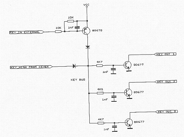
In order to achieve keying in parallel and having isolation between the keying inputs of the transceivers, I have chosen to make a keying serial "bus", which is active high. This bus keys a series of NPN switching transistors, one for each transceiver. The bus is driven from my electronic keyer, which has an active high (inverse) output. Extra inputs to the bus for a handkey or PC interface can be added by means of an inverting circuit (e.g. PNP transistor).
This is the circuit diagram:
IF SWITCHING
In order to bring down the transceiver count, it is natural to use the same transceiver for more microwave bands. I prefer to use separate RX & TX cables for the IF connection to my microwave transverters. This "dual line" approach makes it easier to introduce separate attenuation in the RX or in the TX branch, when there is a need to adjust the signal levels. It also gives more transparency during fault detection on a mast mounted transverter. Furthermore I use split RX & TX cables also on the lower bands, so my transceivers already have separate RX & TX connectors.
I order to speed up the process of QSYing from one band to another, I have built some IF switches. Since separate switches are needed in each branch (RX & TX), and maybe a third switch for the TX control signal, I have chosen low cost DC relays.
These relays do not provide too much isolation on 144/432 MHz, but that is of less importance. I am using small "sugar cube" relays, which have a metal cover, that can be used for grounding.
These relays can be found surplus at reasonable prices, and by using more relays a split of 2,4 or more IF outputs can be provided. If you are using a preamp and a PA on the fundamental band of the transceiver, then even that band could be connected to one of the IF outputs.
The relays could be internal or external to the transceiver, but it is an advantage, if the switching can be controlled from the transceiver. In my ICOM 402 I use the S-meter light switch voltage to switch the relays as well, this gives a good visual indication of which band I am on (e.g. lights off is 6cm, and lights on is 3cm).
MULTIBAND ANTENNAS
In order to make an efficient use of antenna mast space, it becomes desirable to make use of multiband antennas, e.g. a parabolic dish with a multi band feed. If at the same time the transverters have been placed in the mast to minimize cable losses, a need for switching between the antenna and the transverters occurs.
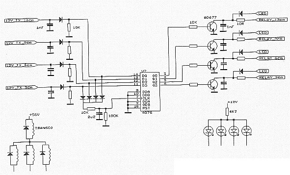
Fortunately multi pole microwave relays are available e.g. TRANSCO 14300, which is a SP4T relay. In order to make the switching as seamless to the operator as possible, I decided to make some control logic, that switches the relay to a given band when the transverter of that band is switched to TX. Afterwards the relay stays in that position until another transverter is switched to TX.
With this system the operator simply has to flick the PTT on a given band to acquire a connection to the multi band antenna. The control logic was realized with D-flip/flops, connecting the TX/RX switching signals (e.g. 12V_TX) output signals of the transceivers to the inputs, and using the RX-to-TX transition of any of the signals to clock the flip/flops. The schematic shows a system for four bands using the TRANSCO relay.